


Fiber Optics FM Modulation
This trainer has been designed with a view to provide practical and experimental knowledge of a general circuit of Fiber Optic FM Modulation/Demodulation on a SINGLE P.C.B
Description
This trainer has been designed with a view to provide practical and experimental knowledge of a general circuit of Fiber Optic FM Modulation/Demodulation on a SINGLE P.C.B
Specification :
1. Power supply requirement : 230V AC, 50 Hz.
2. Built in IC based power supply.
3. On Board Audio signal generator – Sine wave
Frequency : 300Hz to 3.4KHz
Amplitude : 0 to 5Vpp.
4. Transmitter : Fiber optic LED’s (Peak Wavelength of emission 820mm)
5. Receiver : Fiber optic Photo diode
6. Modulation : Frequency Modulation
7. Demodulation : FM Detector and Low pass Filter
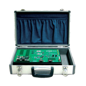
6. All parts are soldered on single PCB of size 12″ x 9″ with complete circuit diagram screen-printed.
9. Standard Accessories : 1. A Training Manual
2. Connecting Patch cords.

Reviews
There are no reviews yet.