Measurement of Speed Using Opto Transducer
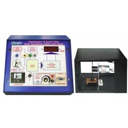
This trainer has been designed with a view to provide theoretical and experimental knowledge of Measurement of Speed using Opto Transducer on a SINGLE P.C.B.
Description
This trainer has been designed with a view to provide theoretical and experimental knowledge of Measurement of Speed using Opto Transducer on a SINGLE P.C.B.
The complete circuit of Measurement of Speed using Opto Transducer is printed on single PCB.
Study of characteristics of Opto Transducer.
Complete Circuit is screen printed on the PCB.
Typical ICs are provided on sockets to provide a facility to check similar other ICs.
Explanation, Observation, Alignment and adjustment of Internal and External controls is possible at a glance due to single PCB.
Easy identification of different parts of Opto Transducer at a glance.
Easy measurement of Voltages and Observation of waveforms at any point. Also typical voltages and waveforms are provided.
A manual having Practical details is provided with the trainer.
The whole circuit of Measurement of Speed using Opto Transducer is explained section wise in detail in the manual.
Specification :
1. Power supply : 230V Ac, 50 Hz.
2. Transducer Type : Infrared LED and Photo transistor.
3. Motor : 12V DC motor with 3600 RMP speed
and 0.3 Kg/Cm2 torque.
4. Motor Mounting : Wheel of 20 teeth mounted on motor shaft.
5. Motor Speed controller : provided to change the speed of motor.
6. Measurement Range : 10000 RPM Max.
7. Output Display : 4 digits Digital frequency Counter calibrated in R.P.M.
8. All parts are soldered on TAGS on SINGLE PCB with complete circuit diagram SCREEN PRINTED.
9. Standard Accessories : 1. A Manual having practical
2. Patch Cords.


Reviews
There are no reviews yet.